Kit one – Chassis and buffer beams
Kit one in a series of 12 – Building a Polly Model Prairie Tank Locomotive
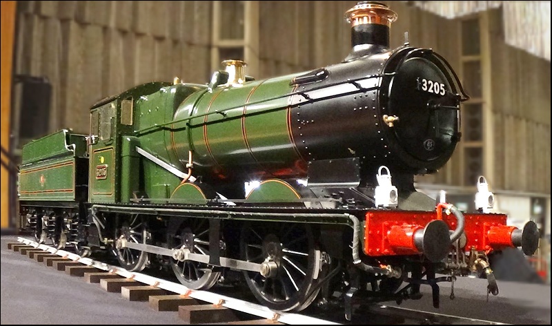
This post, and the subsequent series of posts, follow my journey building a 5″ Live Steam Locomotive. I have never done anything like this before and will be learning the skills needed to complete the model on the way.
I was excited when the kit one arrived; I was surprised by the size and weight of the parts. Initial impressions where high as I felt the quality of parts was extremely good. The kit also included 3 large scale drawings that help to explain how the parts relate to one another.
This first kit was straight forward, just cleaning, sanding, and finessing to ensure a good quality finish. The hardest part was to paint the parts; I opted to use red for the insides of the chassis and black for the outside of the chassis. Overall, I was happy with the results I was able to gain, with very little skill or experience.
As I have built the kits, I have found it useful to view colour pictures from other builders, I hope my pictures help others building, repairing and maintaining Polly Model Engineering locomotives. The main sites I used have been worth a special mention are, Wakelin – Build a Polly V 5” gauge 2-6-0 tank loco, Building a Polly VI locomotive from a kit, Building Molly Ann and A completed model that was sold by the Steam Workshop .
In addition to these great picture and accounts from others building from the same range of kits, I found “Setting up the timing on a Polly V Locomotive” to be invaluable.
This website and blog should be seen as information only, I will be document building the 12 kits, if you need expert advice, please contact Polly Model Engineering.
Need tools – tools I used are listed here…
This is kit 1 of 12. This builds the frames of the Polly Model Engineering Prairie Tank locomotive. This kit is not yet complete, so please check back to see my progress. 1. This is the contents of kit one. I was really impressed by the quality of the parts produced; they al arrived very well packaged. I was also pleased to see the use of a high-quality courier service, delivered as and when expected. I have laid out the items for ease of checking the contents. 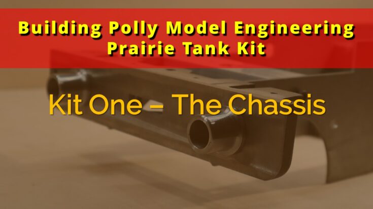
Kit One
Materials
Tools
Instructions

2. This image shows a closer view of the main parts in this kit. 
3. This is a closeup showing the frames with the axle box guides already installed. You can see that “thread locker” has been used to ensure a secure fit. Included in the image is the spring pocket, ready to be fitted to the frame prior to painting. 
4. Buffer body and frame with the fixings required. 
5. The front hook, a cast part that will need little cleaning up, paint or not to paint is the question. I did paint it; I have not yet fitted the chain. 
6. The boiler support before it has been cleaned. 
7. This a trial fit of the main parts, showing the rear part of the loco. I did find that I needed to open out the 4 holes for the hex bolts that hold the pony main stay in place. It took a few passes of a round file to make the bolts fit in place. 
8. Right hand frame, showing the pre installed axle box guides. 
9. Front end of the frames, trial fit. 
10. Trial fit of the rocker shaft bearings (x 2) and the weight shaft bearings (x2). 
11. This is a trial fit of the buffer bodies. You can also the opening for the tow hitch. This needed cleaning up, as it was in a cast metal state. I did not take images pre cleaning up. 
12. This is a trial fit of the buffer bodies the hook on the front buffer beam. The square hole for the hook also needed cleaning up and opening out, as per the instructions. I did not take images pre cleaning up either. This was easily achieved using a multi tool and small files. 
13. This image shows the rear pony main stay. I did find that the holes for the hex bolts were just slightly too small, but after a few light passes of the multi tool and a round file, they fitted perfectly. 
14. This image was taken after I had cleaned up all the parts and assembled them ready for painting. You can see the rear pony pivot block to the right in this image. I did find that both pivots had a very snug fit, especially the rear pivot. This was easily rectified with fine emery cloth. Both pivots now move freely. 
15. I have given a lot of thought on how to get the best possible paint finish on to my loco. I don't see the point of spending a small fortune on a kit, only to ruin it with a poor paint job!
I decided to paint the inside of the frames with a small brush, the instructions recommended using a brand of paint in a smooth version. I did this, but I feel that brushing it has not given the best possible finish. I will use sandpaper to refine the painted surface and spray an new top coat. I am not over concerned at this stage as this paint only needs to protect the metal, it won’t be seen on the finished loco.

16. I did spray the pony main stays with etch primer to ensure I got good paint adhesion to the aluminium. 
17. I painted the front and rear buffer beams without the buffer bodies attached. I will sand these back and spray them with the bodies attached, as before I have not been happy with the brushed finish of the paint. 
18. I painted (brushed) the buffer bodies and the front hook. The buffer bodies I will sand back and spray them. As you can see, I have painted the front hook. I am not sure this was the right thing to do. Only time will tell. 
19. The next task was to mask off the red paint and spray the outsides of the frames with black enamel. I wanted to spray the frames as they are going to be a little more on show. 
20. The front of the loco. 
21. The rear of the loco with the buffer beam taped up. 
22. This shows the frames after I have sanded them back, ready to spray with the top coat of enamel. 
23. Final coat applied, it looks much better in real, the photo does not do it justice, a couple of very small parts to touch in and the frames will be finished, well paint wise that is! 
24. The rear drag bar, this is also complete with just a few small touches to make. 
25. The rockershaft and the weight shaft bearings fitted in place. The instructions place an emphasis on these being tight, due to them being in accessible at a later stage. I will add a little thread locker to ensure they stay in place. 
26. Front buffer beam, completed with just a few small items to touch in. 
27. The empty beams, completed with just a few small items to touch in. 
28. And that's that! The rear buffer beams, only just noted the chip to the right hand buffer body.